
Copy settings from the MODBUS Poll utility to our Modbus Data Logger
Problem scenario:
I can successfully test and read data from my MODBUS RTU device using the MODBUS Poll software. How can I copy a MODBUS query settings to your logger because I would like to export data to a database?
Requirements:
- Data Logger Suite Professional, Enterprise, or a trial version.
It is assumed that:
You can successfully read data from your MODBUS device using MODBUS Poll (fig. 1).
Solution:
1. Create a new configuration from the main window using the "Green Plus" button. (fig. 3). This example shows the connection settings for MODBUS RTU. If your device uses MODBUS TCP, look here. First, copy the communication settings from MODBUS poll (Connection → Connect, fig. 1, 2):
- COM port, Baud, Data bits, Parity, Stop bits.
- Spy mode - disable this option.
- RTS toggle (fig. 2) → RS485 mode. Enable this option, if you've connected your MODBUS devices to an RS-485 bus, and you use RS485-USB or RS485-RS232 converter.
- DTR → Data flow control → Use DTR.
- DSR/CTS → Data flow control → Require DST/CTS.
- Other options - leave the default value as shown below.
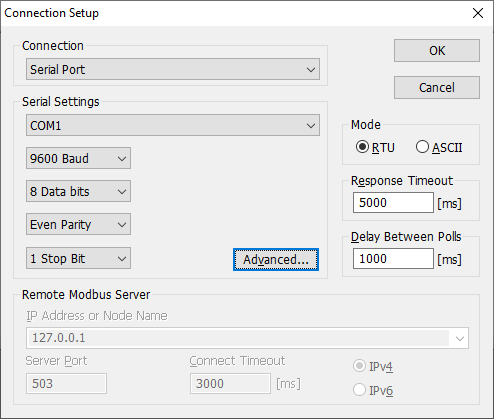
Fig. 1: MODBUS Poll Connection Setup.
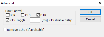
Fig. 2: MODBUS Poll Advanced Setup.

Fig. 3: MODBUS Data Logger Connection Setup.
2. Activate the "MODBUS RTU" plugin in the settings in both fields "Data query module" and "Parser module". Please do not confuse it with "MODBUS RTU [Passive]" or "MODBUS RTU [Slave]" because they realize other functionality. We configure the MODBUS master station.

Fig. 4: Activating the MODBUS RTU plugin.
3. In the MODBUS RTU plugin settings, click the "Action → Add new request" button to add a new query request (fig. 6). Copy basic request settings from MODBUS poll (Setup → Read/Write Definition, fig. 5):
- Slave ID → Device address.
- Function → Function.
- Address (Dec) → First register - Value.
- Quantity → Registers to read.
- Response timeout (fig. 1) → Request timeout (ms).
- Scan rate → Polling interval.
Note: The figure 6 is an example. It does not match the settings on figure 5.

Fig. 5: MODBUS poll: Basic MODBUS query settings.

Fig. 6: Logger: Basic MODBUS query settings.
4. Add only one response item by clicking the "Action → Add response item" button if it does not exist in the list (fig. 8).
- Name - any name of this value.
- Offset - it is the byte offset in response data without a device address, function code and data size. Set this value to "-1", and the program will calculate an offset automatically.
- Count - the number of sequential values with the identical data type and name. This value depends on "Registers to read" and "Data type". One register contains 16 bits. So, Count = Registers to read * 16 / Bits in value.
- Append counter - it is used when "Count" is greater than 1.
- Data type - copy the data type from the "Display" menu (fig. 7).
- Unsigned - enable this option if a data type in MODBUS Poll is unsigned.
- Little-endian - it is the same as the "Little-endian" option in MODBUS Poll.
- Swapped - it is the same as the "Byte swap" option.
Note: The figure 8 below is an example. It does not match response items on fig. 5 and 7. The correct definition for the "Signed 32 bit, big-endian" data type in MODBUS Poll:
- Name: VALUE, Offset: -1, Append counter: On, Count: 5, Data type: Decimal 32 bit, Unsigned: Off, Little-endian: Off, Swapped: Off.
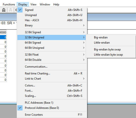
Fig. 7: MODBUS Poll: Display.

Fig. 8: MODBUS response items.
FAQ
How can I poll multiple MODBUS RTU devices?
MODBUS RTU allows you to connect up to 254 devices on one RS-485 bus. You may specify several addresses like 1,2,3,4,5 in the "Device address" field (fig. 3).
Can I poll MODBUS TCP devices?
Yes, of course. The settings are almost identical. You should configure the TCP connection settings and select other parser type (MODBUS TCP instead of MODBUS RTU on step 2).
Related articles: Copy settings from the MODBUS Poll utility to our Modbus Data Logger
MODBUS RTU, MODBUS ASCII, MODBUS/TCP
- MODBUS power meter data logging (easy method)
- Sunspec-compatible MODBUS power meters, inverters (easy method)
- MODBUS RTU/TCP polling: Configuring master station Tags: MODBUS RTU, MODBUS TCP, requests, response items.
- MODBUS poll: How to make sure that the application sends requests and receives responses?
- MODBUS poll: How to view register values, not raw MODBUS packets?
- MODBUS polling: How to make sure that the application correctly interprets the responses received from the device?
- MODBUS polling: How to view MODBUS register values in a more easy-to-grasp form (graphs, indicators, etc.)?
- MODBUS: How to combine the data of two requests?
- MODBUS: What is the right way to poll multiple devices?
- Copy settings from Simply MODBUS RTU Master to our Modbus Data Logger.
- Copy settings from the MODBUS Poll utility.
- Controlling PLC coil registers status using MODBUS TCP Tags: MODBUS data parser, custom scripts, events generating, and handling.
- MODBUS to MSSQL: Write MODBUS registers to separate columns
- MODBUS to MySQL: Write MODBUS values to the MySQL database
- MODBUS to a database: Writing MODBUS RTU/TCP values to a database
- MODBUS to a database: Write data to two different tables.
- MODBUS to a database: Write data to two different databases, making a complete copy.
- Sentron PAC 3200: MODBUS TCP Data Logging
- Write data to a MODBUS device
- SQL to MODBUS: Send data from a SQL database to MODBUS.
- MODBUS TCP ↔ MODBUS RTU real-time conversion.
BACNET/IP
IEC 62056-21
- IEC 62056-21 power meter data logging Tags: Iskra Emco, Satec, Landis+Gyr.